Pages

Showing posts with label gpu. Show all posts

Visibility Buffer

 I rewrote the main render to use a visibility buffer, if you are unfamiliar with this, it is a renderer whose first pass has a very simple pixel shader that writes out the draw call ID & triangle index.

Given the high triangle count I figured the visibility buffer would perform better since it cancels out much of the 2x2 overshade issue that arises with tiny triangles, and this turned out to be very correct. 

The game now runs significantly faster, and is also much more portable, as I don't have to rely on driver extensions to get access to barycentrics.

 My visibility buffer is 32 bit, 14 bits for the triangle ID, and 18 for the draw call ID.  This did require limiting triangles counts to 14 bit, which was not an existing requirement, but was simple enough to add.


Quasi Virtual Texturing System


This is an overview of a quasi virtual texturing system that I implemented for my game.

I use this system instead of a traditional virtual texturing system for the following reasons.

  1. Supports all levels of anisotropic/trilinear filtering, even on old hardware
  2. Doesn’t use tiled resources which require newer GPUs, and aren’t available on Windows 7 with d3d11
  3. I use triplanar texturing exclusively, and do not have traditional UVs

Algorithm

This algorithm uses multiple texture arrays, and a structured buffer that indicates per material, which array to sample from.

It uses a fixed sized amount of memory for textures on the GPU.

Textures are limited to square powers of 2, the only sizes supported are 256,512,1024, and 2048. This reduces the number of arrays we will need to a reasonable number.

I pre-generated a texture array that contains all of the mips of size 256 and under, for all textures.

I also allocate fixed sized arrays for 512,1024 and 2048; with the larger sizes having progressively fewer slots.

Number of slots : Here are the number of slots I have per array, these numbers are mostly arbitrary.

  • 256: # of textures
  • 512: 128 slots
  • 1024: 32 slots
  • 2048: 8 slots

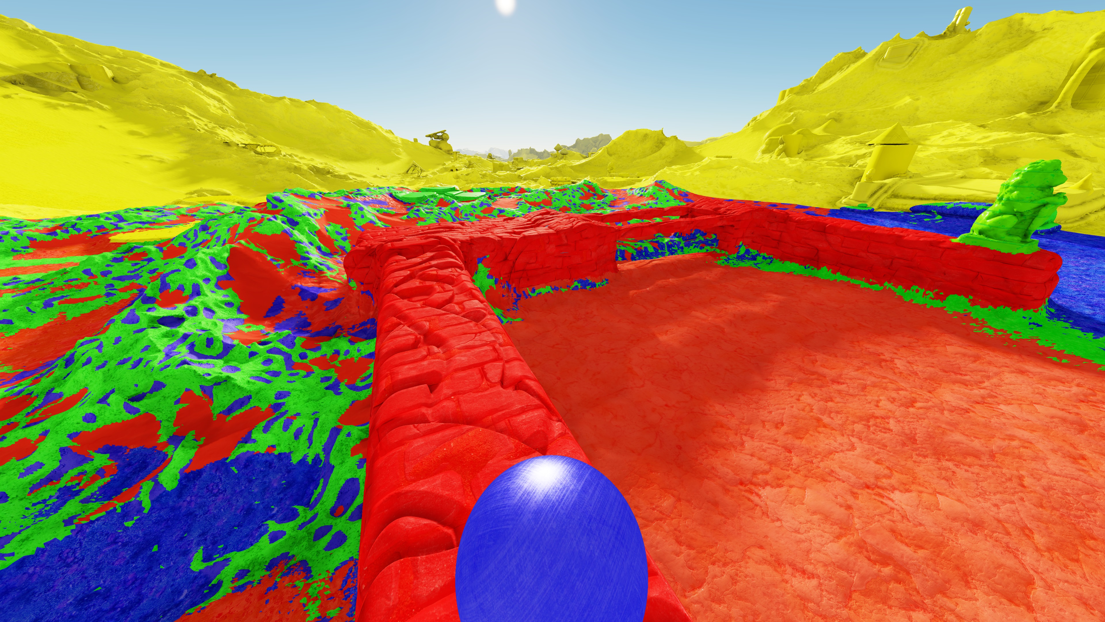
Here is a visualization of the arrays.

SDFShape2 

 Yellow is 256, Green is 512, Blue is 1024, and Red is 2048.
I force everything to use 256 past a certain distance to reduce divergence

A structured buffer is used as an indirection mapping; pass in the material ID, and retrieve which array to sample from, and which slot in the array.

Prioritizing Textures

As there is a limited number of high resolution textures that can be on the GPU at any given time, a system to was needed to determine which textures should be resident.

This is done by storing the N most important textures, along with a score, for each voxel patch.

The score is simple the number of vertices that reference the texture.

Each frame, for visible patches, the score is added to the appropriate textures/MIP based on the distance from the camera for the patch.

Patches which are out of the frustum or occluded do not get added.

The textures/mip with the highest score, that is not resident on the GPU is then considered for uploaded, if it has a higher score than a resident texture at the same mip level.

Only one texture is uploaded per frame, to limit the amount of data that needs to be transferred.

The structured buffer is also updated to reflect where the GPU can find the texture.

Latency is reduced by having the CPU side also store a cache of recently accessed textures, the caches size is adjustable, but is currently set to 300mb.

Results

The system works well and transparently pages in texture data based on visibility.

It never suffers from horribly blurry textures since the 256 mips are always available as a fallback.

Even standing still and turning the camera around can and will cause textures to be paged in/out.

Limitations

  • D3d11 has a max texture array size of 2048. This means this system can only support 2048 separate materials. I am nowhere near this limit, so this isn’t an issue for me.

Faster Triplanar Texturing

Here is a method I created to improve performance when using Triplanar texturing.
I also think it looks better.


So the standard triplanar texturing algorithm you will find in varous places on the internet looks something like this.

float3 TriPlanarBlendWeightsStandard(float3 normal) {
float3 blend_weights = abs(normal.xyz); 
blend_weights = (blend_weights - 0.55);
blend_weights = max(blend_weights, 0);   
float rcpBlend = 1.0 / (blend_weights.x + blend_weights.y + blend_weights.z);
return blend_weights*rcpBlend;
}

If we visualize the blend zones this is what it looks like.


Red/Green/Blue represent one texture sample.

Yellow/pink/cyan represent two textures samples.

And in the white corner we need all three.

As we can see the blend width is not constant, it is very small in the corner and quite wide along axis aligned edges.

The corner has barely any blending as we have pushed our blend zone out as far as possible by subtracting .55.(anything over 1/sqrt(3) or 0.577 results in negative blend zones in the corner).

This results in needless texture sampling along aligned edges, stealing away our precious bandwidth.

Constant Blend Width


What we want is something more like this-- constant blend width.

We do this by working in max norm distance instead of euclidean,  as our planes are axis aligned anyway--

Here is the modified code that generates this:
float3 TriPlanarBlendWeightsConstantOverlap(float3 normal) {

//float3 blend_weights =  abs(normal);
float3 blend_weights = normal*normal;
float maxBlend = max(blend_weights.x, max(blend_weights.y, blend_weights.z));
blend_weights = blend_weights - maxBlend*0.9f;

blend_weights = max(blend_weights, 0);   

float rcpBlend = 1.0 / (blend_weights.x + blend_weights.y + blend_weights.z);
return blend_weights*rcpBlend;
}


 You can adjust the blend width by changing the scalar .9 value.

On my GPU the constant version runs slightly faster, likely because there are less pixels where more than one texture sample is required.

I believe it also looks better--as there is less smearing along axis aligned edges.


Here is a shadertoy I created if you want to play with it


Barycentric Coordinates in Pixel Shader

 EDIT: this is out of date, it is better to use visibility buffer and manually calculate barycentrics

Recently I was in need a way to perform smooth blending between per vertex materials.

Basically I needed barycentric coordinates + access to each vertices material in the pixel shader.

Unfortunately this isn’t built into the common rendering APIs, and so requires some extra effort.

Here is a list of some possible solutions:

Geometry Shader: Assign the coordinates: (1,0,0), (0,1,0), (0,0,1) to the vertices of the triangle. Also write the three materials to each vertex. This method is easy to implement but has terrible performance on many cards, since it requires a geometry shader. When enabled on my AMD card, FPS drops to half or less.

The following two methods are D3D11/12 focused

AMD AGS Driver extension: AMD has a library called AGS_SDK which exposes driver extensions, one of these is direct access to barycentric coordinates in the pixel shader. It also allows for direct access to any of the attributes from the 3 vertices that make up the triangle. This method is very fast and works well if you have an AMD card that supports it.

 float2 bary2d = AmdDxExtShaderIntrinsics_IjBarycentricCoords(AmdDxExtShaderIntrinsicsBarycentric_PerspCenter);
 //reconstruct the 3rd coordinate
 float3 bary = float3(1.0 - bary2d.x - bary2d.y, bary2d.y, bary2d.x);

//extract materials
 float m0 = AmdDxExtShaderIntrinsics_VertexParameterComponent(0, 1, 0);
 float m1 = AmdDxExtShaderIntrinsics_VertexParameterComponent(1, 1, 0);
 float m2 = AmdDxExtShaderIntrinsics_VertexParameterComponent(2, 1, 0);

Nvidia FastGeometryShader: Nvidia also have driver extensions NVAPI, and one of these is the the “fast geometry shader” for when you only need a subset of the features geometry shaders offer. It should be possible to use this to pass down barycentric coordinates & materials, but I do not have an Nvidia card to test this on.

Embed Into Vertex Data: Another option is to enlarge the vertex, and embed the barycentric coordinates and the 3 materials directly into it. This is probably a better fallback than the GS, although it does have the downside of reducing vertex reuse, since many vertices that were previously identical would now differ.

Domain Shader?: I haven’t tried this method, but I think it might be possible to pass down barycentric coordinates from a domain shader

Visual Comparison

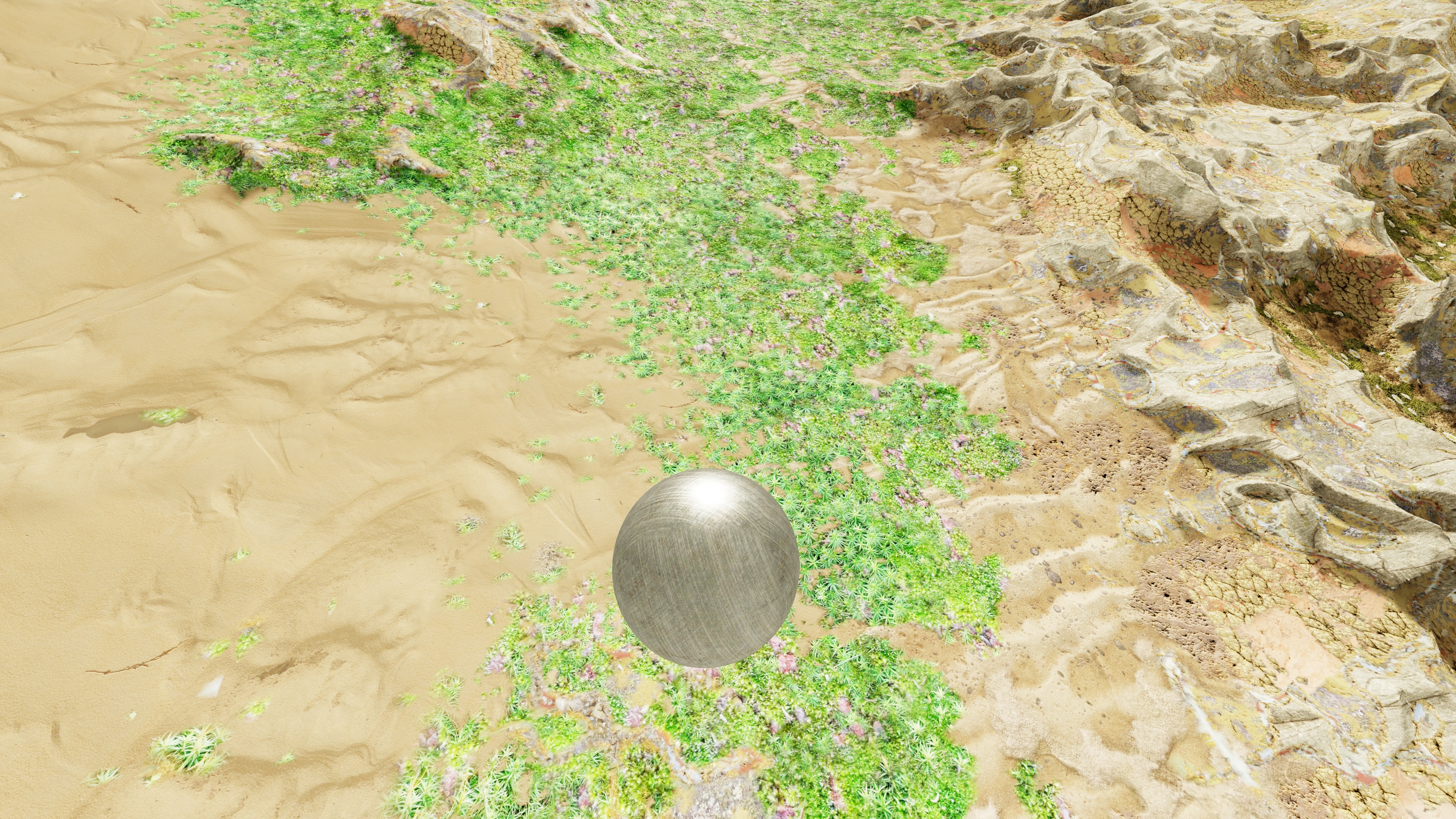
BaryOn 

 Ground rendered using barycentrics to perform smooth blending between materials

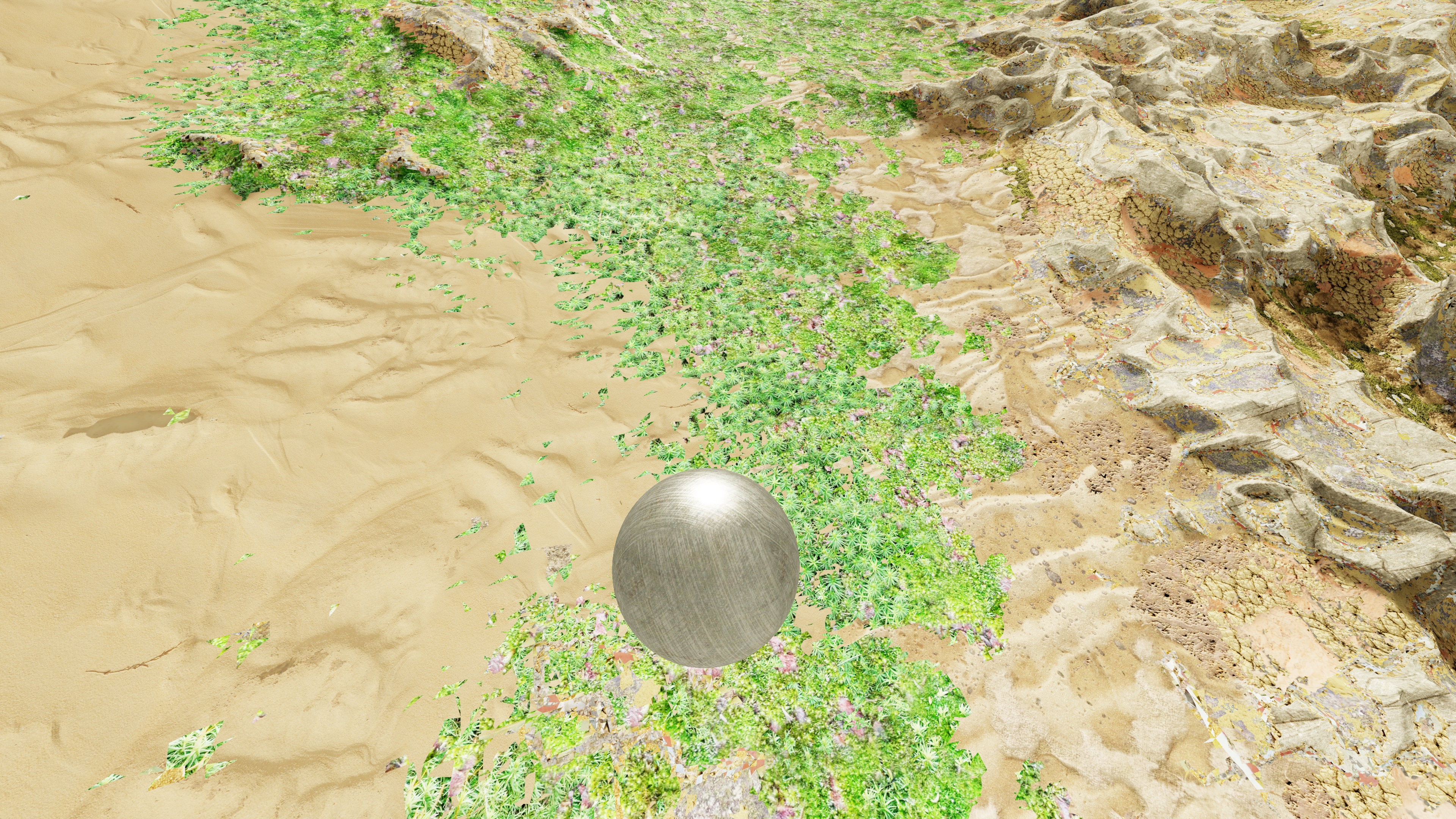
BaryOff 

 Ground rendered without barycentrics, the material is selected from the base vertex and there is no blending between materials